peak cell rate applies to what for atm connections?

Table of Contents
ATM Connections
- Introduction
General Description
ASI Card Features
Connection Routing
ATM Layer Processing
Traffic Management for the ASI-1 (T3/E3)
ATM Connections
Introduction
This chapter provides further information on ATM network connections and related functions. The chapter also discusses ATM connection topics such every bit features, configuring, types, etc.
Full general Description
ATM services are established in StrataCom broadband networks by calculation ATM connections between ATM Service Interface ports in the network. ATM permanent virtual circuits (PVCs) tin can originate and terminate on the ATM Service Interface cards on the BPX, or on the AXIS shelf (with the introduction of the AUSM card for the AXIS).
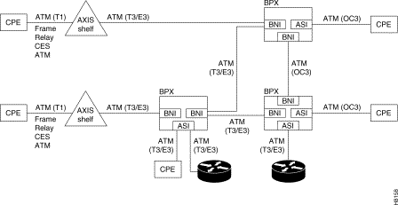
is a simplified depiction of ATM connections over a BPX network. It shows ATM connections via ASI-1 and ASI-155 cards, as well as over Centrality shelves. It also shows frame relay to ATM interworking connections over AXIS, IPX, and IGX shelves. For further information on the Centrality shelf, refer to the Centrality Reference Manual. ATM Connections over a BPX Network.
Figure five-i: ATM Connections over a BPX Network
ASI Card Features
The ATM Service Interface Cards for the BPX are the ASI-1 and ASI-155 card sets which provide for the termination of ATM connections in an ATM network.
ASI-1 Features
The ASI-one is a 2-port DS3 access service interface menu (ATM-UNI) for the BPX switch. The ASI-1 bill of fare fix consists of the following:
- ASI-i Front Card
- Back Cards
- LM—2T3
- LM—2E3
The following lists the features available with Release viii.ane of the ASI-1 card set and organisation software. Later releases will include additional features.
- Virtual Path besides as Virtual Circuit connections.
- Support for 1000 connections per ASI-1 card and yard connections (ungrouped) or 5000 connections (grouped) per BPX node.
- 2 DS3 ATM ports.
- UNI (User-to-Network Interface) and NNI (Network-to-Network Interface) protocols.
- Automatic routing of new and failed connections (AutoRoute).
- Usage Parameter Control using leaky bucket algorithm to command admission to the network.
- Selective Cell Discard.
- Per virtual circuit ingress queues.
- Per QOS egress buffers.
- 3-connection types: CBR, VBR, and ABR.
- ATM cell construction and format per ATM Forum UNI v3.i.
- End-to-end OAM flows and terminate-to-end loopback per ATM Forum UNI v3.i
- External segment flows consisting of segment loopback cells per ATM Forum UNI v3.1
ASI-155 Features
The ASI-155 is a 2-port OC3 SONET/SDH access service interface card (ATM-UNI) for the BPX switch. The ASI-155 menu prepare consists of the following:
- ASI-155 Forepart Card
- Back Cards
- LM-2OC3-MMF-2-BC (multi-mode fiber)
- LM-2OC3-SMF-2-BC (unmarried-mode cobweb intermediate range)
- LM-2OC3-SMFLR-2-BC (unmarried-mode cobweb long accomplish)
The following lists the features available with Release 8.1 of the ASI-155 card set and system software. Later releases volition include boosted features.
- Virtual Path likewise as Virtual Excursion connections.
- Support for 1000 connections per port for each of the 2 ports on the ASI-155 card and m ungrouped or 5000 grouped connections per BPX node.
- Two port OC3 SONET/SDH ATM ports operating at a 155.52 Mbps rate (353,208 cells per 2nd).
- UNI (User-to-Network Interface) and NNI (Network-to-Network Interface) protocols.
- Automatic routing of new and failed connections (AutoRoute).
- Usage Parameter Command using leaky saucepan algorithm to control access to the network.
- Selective Prison cell Discard.
- Per virtual circuit ingress buffers.
- Per QOS egress buffers.
- 2 connection types: CBR and VBR.
- ATM cell construction and format per ATM Forum UNI v3.one.
- End-to-end OAM flows and terminate-to-end loopback per ATM Forum UNI v3.1.
- External segment flows consisting of segment loopback cells per ATM Forum UNI v3.one.
ASI Carte Clarification
ASI-1
Each ASI-1 provides two ports for ATM connections with a T3/E3 line interface for connection to user devices. These ports are used for User-to-Network (UNI) as well every bit Network-to-Network (NNI) Interfaces.
These ports process the ATM data at the Concrete Media Dependent (PMD) and Transmission Convergence (TC) sub-layers in accord with the ITU-T and ATM Forums protocol layer models. The TC layer is besides referred to as the Physical Layer Convergence Protocol (PLCP).
Each DS3 port supports an ATM jail cell rate of 96,000 cells/sec. (E3 ports support fourscore,000 cells/sec.) Timing is sourced from the BPX only at this fourth dimension. A 64,000 cell ingress buffer is shared betwixt the two ports on the ASI.
ASI-155
The ASI-155 provides two OC-3/STM- 1 Multi-Mode Cobweb/Single Mode Cobweb Back ports for connectedness to user devices. The ASI-155 will provide additional interface types in future releases. These ports are used for both User-to-Network (UNI) as well every bit Network-to-Network (NNI) Interfaces.
ATM Service Types
The 3 categories of ATM service types provided by the ASI-1 are:
- Abiding Bit Rate (CBR)
- Variable Fleck Charge per unit (VBR)
- Available Fleck Rate (ABR)
The two categories of ATM service types provided by the ASI-155 are:
- Constant Bit Rate (CBR)
- Variable Bit Charge per unit (VBR)
CBR uses fixed bandwidth. CBR traffic is more time dependent, less tolerant of delay, and generally more deterministic in bandwidth requirements. Vocalization and high-resolution video are typical examples of traffic utilizing this type of connectedness.
VBR and ABR are of a bursty nature that utilizes network bandwidth intermittently but ofttimes require large amounts of bandwidth when active. Filibuster is commonly not a major consideration as long as information technology does non become excessive.
VBR uses a variable amount of bandwidth, simply bandwidth must nevertheless be reserved to run into QOS requirements.
ABR applies the optional ForeSight congestion management characteristic to variable flake rate traffic. ForeSight is a charge per unit-based, dynamic, closed-loop feedback congestion control mechanism. The ForeSight congestion direction feature provides more throughput with less network congestion than for connections operating without it.
If desired, all three service types may be intermixed inside the network or fifty-fifty within connections originating on the same node or bill of fare. Connection classes are templates that are practical as each connection is added to the network. Boosted connection classes, upwards to 32 (ASI-1) or up to 12 (ASI-155) tin can be defined as needed in the future.
Connection Routing
ATM connections are identified equally follows:
- slot number (in the BPX shelf where the ASI is located)
- port number (one of two ATM ports on the ASI)
- Virtual Path Identifier (VPI)
- Virtual Circuit Identifier (VCI)—(* for virtual path connections).
The slot and port are related to the BPX hardware. Virtual path connections (VPCs) are identified by a "*" for the VCI field. Virtual circuit connections (VCCs) are identified past both a VPI and VCI field.
For VCCs, the allowable VPI field is from 0-255 (UNI) or 0-1023 (NNI), and the allowable VCI field is from 0 to 65535. For VPCs, the high guild four bits of the VCI are masked by the ASI, restricting the VCI range to 0-4095.
The ASI-1 card supports grand PVCs and an ASI-155 card supports 1000 PVCs per port. A BPX node tin support grand ungrouped PVCs or 5000 grouped PVCs.
Connections added to the StrataCom network are automatically routed one time the end points are specified. This AutoRoute characteristic is standard with all BPX and IPX nodes. The network automatically detects torso failures and routes connections effectually the failures.
ATM Layer Processing
The ATM cells carried on the ATM connections are assumed to exist in the format and have the structure compliant with ITU-T Recommendation I.361 and ANSI T1S1.5/92-002R3
ASI-1: Cells with HEC errors, including single bit errors, are dropped and a PVC statistic is incremented. Cells with non-naught GFC are admitted, and a PVC statistic is incremented.
The Prison cell Loss Priority setting is enabled on a per-connection basis for the ASI-i. Cell Loss Priority indicates to the network that cells are candidates for discard if they encounter network congestion. The CLP flake may be ready, per user selection for incoming cells, if the applicable leaky bucket is filled. If the CLP bit is gear up to ane, so the jail cell may be discarded if it encounters congestion downstream.
ASI-155: Single-bit HEC errors are corrected by the ASI-155, but no channel statistics are kept. At that place is no non-nix GFC counter on the ASI-155. The CLP scrap may be set up, per user option, for incoming cells if the leaky bucket is filled. If the CLP scrap is set up to 1, then the cell may be discarded if congestion is encountered downstream. The Resources Management (RM) choice is not used past the ASI-155.
Traffic Management for the ASI-i (T3/E3)
As specified in ITU-T (CCITT) standards, the BPX offers multiple levels of traffic control and resource management.
AutoRoute(TM) is the automatic routing and re-routing of connections and is proprietary to StrataCom.
OptiClass(TM) offers upwardly to 32 programmable service classes. For ATM connections, CBR, VBR, and ABR classes are used on the BPX with up to 32 classes bachelor.
FairShare(TM) provides per-PVC queueing and per-PVC scheduling and provides fairness in servicing connections and firewalls between the connections. Firewalls foreclose a non-compliant connection from affecting the QoS of compliant connections.
With UPC (Usage Parameter Control) enabled for a connexion, incoming prison cell traffic is monitored for compliance with configurable traffic parameters.
Congestion management may be provided past Selective Cell Discard or by ForeSight(TM) which provides a dynamic closed-looped rate-based congestion command mechanism for bursty traffic.
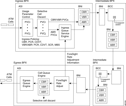
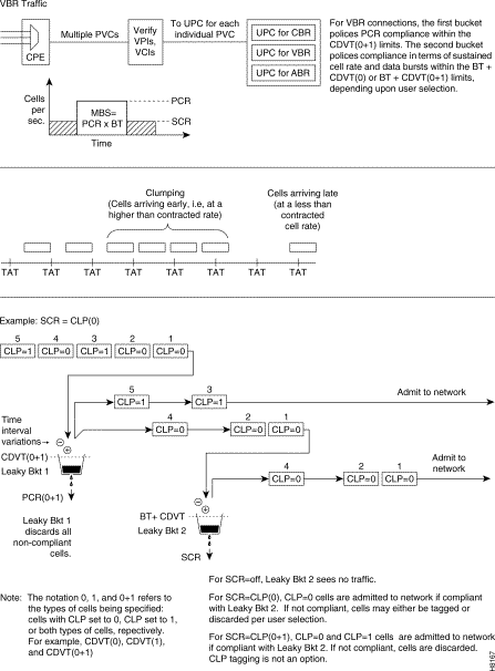
Figure 5-2 shows a simplified example of ATM prison cell traffic across a BPX network. At the network ingress node, UPC policing, selective prison cell discard, private PVC queuing, and the ForeSight congestion control functions are performed. At the intermediate nodes, PVCs are enqueued according to their ATM Service classes (CBR, VBR, or ABR) and congestion information is carried forwarded to the egress BPX node.
At the egress node, selective cell discard is performed, and PVCs are enqueued according to their ATM Service classes (CBR, VBR, or ABR).
For ABR connections, ForeSight congestion information is fed back from the egress node to the ingress node to provide dynamic adjustment of the rate at which the ATM cells are admitted to the network past the ingress node.
Figure 5-2: Simplified Example of ATM Traffic Management
Admission Controls (UPC), ASI-1 (T3/E3)
The ASI ports must provide some control on the input data from the user device to assure fair allocation of the network bandwidth amidst all users. These controls are adjusted based on the blazon of connectedness, CBR, VBR, or ABR for the ASI-1.
A feature of the ASI, Usage Parameter Command (UPC), is applied to the cells for each PVC. Basically, UPC determines if the cell qualifies for admission to the network.
The policing and tagging of the jail cell equally compliant is based on the Generic Cell Rate Algorithm (GCRA) defined by Annex 1 of ITU-T I.371. GCRA is a "continuous leaky-saucepan" process that monitors the cell depth in the input queue for each PVC to determine whether to admit the new cell or not. The ASI sets the CLP bit to 1 for all not-compliant cells. Alternatively, the ASI can drop non-compliant cells rather than tag and admit them. The ASI allows the user a choice between the cell-based GCRA and an enhanced, frame-based, FGCRA. Selecting FGCRA allows an entire frame to be discarded if whatsoever of its cells are non-compliant, rather than transmitting a partial frame over the network.
Policing is established by the parameters that are configured when a PVC is added. These parameters are based on the service contracted for past the user.
CBR policing is based on:
- PCR (Peak Jail cell Rate)
- CDVT (Cell Filibuster Variation Tolerance)
VBR policing is based on:
- MBS (Maximum Burst Size)
- CDVT (Cell Delay Variation Tolerance)
- PCR (Tiptop Jail cell Rate)
- SCR (Sustainable Cell Charge per unit)
ABR policing:
ABR policing is identical to that for VBR. However, for ABR connections, the cells are not admitted directly to the network post-obit policing, just rather are enqueued. They are and then admitted to the network at MCR (every bit a minimum rate) up to PCR (equally a maximum rate), depending on the dynamics of the bachelor network bandwidth.
Congestion Management
The user has a selection of 2 mechanisms for minimizing network congestion that results from simultaneous bursts of data from the user on multiple connections. Selective Prison cell Discard is a relatively simple, passive mechanism and offers no extra bandwidth to the user when it may be available. ForeSight, on the other manus, is a charge per unit-based, dynamic airtight-loop mechanism that automatically provides the user extra bandwidth when there is network bandwidth to spare.
Selective Cell Discard
Selective Cell Discard is performed on each PVC in accordance with ATM Forum UNI 3.1 Specification. A prison cell is discarded under ane of two conditions:
- PVC queue depth has been exceeded
- PVC CLP threshold has been exceeded, and non-compliant or tagged cells are received.
ForeSight for ATM
If ForeSight is enabled, the PVC is serviced (allocated bandwidth) at a variable rate. ForeSight connections include the following configurable parameters:
- Minimum Cell Rate (MCR)—the minimum rate at which a connexion tin can exist served at any fourth dimension during normal network operating conditions.
- Peak Cell Charge per unit (PCR)—the maximum rate at which the connection can be served.
- Initial Cell Rate (ICR)— the charge per unit at which the connection will exist served afterward being idle for a time defined by the ICR Timeout Period (ICR TO).
If a ForeSight connection has been idle for a very brusque time (less than its ICR TO), it will resume transmitting at its previous rate. A ForeSight connection that has been idle for some fourth dimension (greater than its ICR TO) is allowed to outburst data out from its input queue at its ICR. If at that place is no congestion detected on the network, the charge per unit is increased in modest steps until it reaches the PCR or congestion becomes credible. When congestion is detected, the rate is decreased to the MCR or until congestion disappears, whichever occurs showtime.
EFCI
The Explicit Frontwards Congestion Indicator (EFCI) bit, is set in the transmitted prison cell header if the user-programmed EFCI threshold is exceeded. This bit simply serves to notify downstream ATM equipment that this cell has experienced congestion somewhere forth the network. The ASI-one does not deed on this flake. The EFCI flake is the second flake in the Payload Type field.
Port Configuration
Port Configuration for the ASI-1
The ports on an ASI-1 carte du jour are defined by the post-obit parameters. These parameters can be observed using the dspport command and changed using the cnfport command.
Port Type—defines whether the port connects to a user device (UNI) or to another network (NNI).
%Utilization, VBR/ABR Fairness Characteristic for ASI-1 Ports
Enables/disables percent utilization. This parameter supports fairness for ASI terminated connections and applies only to ABR and VBR connections.
When this feature is disabled, the port queue bandwidth is calculated using the sum of the MCRs or PCRs for the connections terminating on the port. This is identical to the port queue bandwidth calculation prior to the implementation of the %util feature.
Port queue bandwidth with %util feature disabled:
- For ABR connections, port queue BW = sum (MCR)
- For VBR connections, port queue BW = sum (PCR)
- For CBR connections, port queue BW = sum (PCR)
When this feature is enabled, the port queue bandwidth is calculated using the sum of a percent of the MCRs or PCRs for the ABR or VBR connections terminating on the port, respectively. This feature is non applied to CBR connections.
Port queue bandwidth with %util feature enabled:
- For ABR connections, port queue BW = sum (MCR * %util)
- For VBR connections, port queue BW = sum (PCR * %util)
- For CBR connections, port queue BW = sum (PCR)
Protocol—selects the port management protocol to be used (Table 5-1).
Table 5-1: Signaling Protocols Supported
| Choice | Protocol Used |
|---|---|
| N | None |
| L | LMI |
| I | ILMI |
Egress Q Depth—Specified for each of three queues for each port. Specifies the maximum output queue size, in cells, reserved for the traffic class. A total of 24,000 cells are shared between all queues on the two ports on a card. Each port can has a maximum capacity of 12,000 cells.
Explicit Forrad Congestion Indication threshold—aforementioned as for Connection Parameters.
CLP Threshold High—configurable for each of the 3 egress queues: CBR, VBR, and ABR for each port.
CLP Threshold Low—configurable for each of the three egress queues: CBR, VBR, and ABR for each port.
Protocol Parameters—If LMI or ILMI is enabled for the port, a number of port parameters may exist modified to accommodate the user device attached to the port.
These parameters are listed in Table five-two and Table v-3.
Tabular array 5-2: LMI Parameters
| Parameter | Default | Clarification |
|---|---|---|
| VPI for LMI connection | 0 | |
| VCI for LMI connexion | 31 | |
| LMI Polling Enable | n | |
| LMI Status Enquiry Timer T393 | 10 | |
| LMI Update Status Timer T394 | 10 | |
| LMI Polling Timer T396 | 10 | |
| LMI Status Enquiry Retry N394 | five | |
| LMI Update Condition Retry N395 | 5 |
Table v-3: ILMI Protocol Parameters
| Parameter | Default | Description |
|---|---|---|
| VPI for ILMI connectedness | 0 | |
| VCI for ILMI connection | 16 | |
| ILMI Polling Enable | due north | Enable ILMI polling |
| ILMI Trap Enable | n | Enable ILMI traps |
| Polling Interval T491 | xxx | |
| P Fault Threshold T491 | 3 | |
| Effect Threshold N492 | four |
Port Configuration for the ASI-155
The ports on an ASI-1 carte du jour are defined by the post-obit parameters. These parameters can exist observed using the dspport control and changed using the cnfport command.
Port Type—defines whether the port connects to a user device (UNI) or to some other network (NNI).
Interface—MMF-2, SMF
Type—NNI, UNI
Speed—
VBR Queue Depth—
Protocol—Same every bit for ASI-1 for LMI and ILMI
Configurable Connection Parameters, ASI-one
There are a number of parameters associated with ATM connections that are user-configurable. The following paragraphs describe the parameters used to configure ATM connections on the ASI-i, including the dual-leaky bucket GCRA parameters.
UPC Policing
The ASI-1 (T3/E3) employs the ATM Forum 3.1 dual-leaky bucket GCRA mechanism for policing of jail cell streams seeking entrance to the network.
Notation The ASI-155 employs a unmarried leaky saucepan GCRA mechanism for policing of cell streams seeking entrance to the network.
Each PVC (VPC or VCC) is policed separately, providing fire walling between connections, and assuring that each connection uses only a fair share of network bandwidth.
Policing for ASI-1 connections is implemented using the ATM Forum's standards—Compliant Dual Leaky saucepan algorithm. Each saucepan is a GCRA (Generic Rate Algorithm) defined past two parameters:
- Charge per unit (where I, expected arrival interval is divers every bit 1/Charge per unit)
- Deviation (L)
If the cells are clumped too close together, the deviations from the normal are added to the saucepan, if other cells get in later on their expected arrival time, then the bucket level goes downwardly.
Dual-Leaky Bucket (First Analogy)
The GCRA bucket function can be considered to office as follows:
i. When a cell arrives, the amount of time that has passed since the terminal compliant jail cell inflow is determined.
ii. The leaky bucket (fourth dimension-bucket) is and so reduced past a quantity (i.e., the bucket "leaks" this much time.)
3. If the quantity of time in the bucket exceeds the limit 50, then the cell fails the GCRA.
4. If the quantity of time in the bucket is less than the limit, and so a value of I is added to the saucepan, where I is 1/rate, or the expected inflow fourth dimension of the cells.
Dual-Leaky Saucepan (Another Illustration)
Some other GCRA viewpoint is as follows:
- For a stream of cells in an ATM connexion, the prison cell compliance is based on the theoretical inflow fourth dimension (TAT).
- The next TAT should exist the time of arrival of the current prison cell plus the expected inflow interval (I) where I = i/rate.
- If the side by side cell arrives before the new TAT, then the accrued penalty of the PVC is incremented by the corporeality of fourth dimension the cell arrived early.
- If the adjacent cell arrives afterward the new TAT, then the accrued punishment of the PVC is decremented past the amount of time the cell arrived belatedly. The accrued punishment is not decremented to less than zero.
- If the accrued penalisation grows beyond the limit (50), then the prison cell fails the GCRA.
For CBR traffic, both dual leaky buckets are policed based on:
- PCR (Meridian Cell Rate)
- CDVT (Cell Delay Variation Tolerance
For VBR traffic, leaky bucket one and leaky bucket 2 are policed based on:
- PCR and CDVT for Leaky Saucepan 1 (GCRA 1)
- SCR, CDVT, and MBS for Leaky Bucket 2 (GCRA 2)
CBR Connections, ASI-1 (T3/E3)
Constant bit rate (CBR) connections are those that cannot tolerate delays of whatever significance. These connections include vocalism and video, etc.
A quality of service QoS contract for CBR would include depression delay, and a abiding input rate. All cells will be served so long as the connection does not exceed its constant rate. A CBR connexion is specified to be transmitted beyond the network at a fixed charge per unit. This charge per unit is specified as PCR, peak cell rate. The rate of the connectedness is immune to vary slightly within the limits specified by CDVT (cell delay variation tolerance).
The parameters applicable to a CBR connexion are shown in Figure 5-3. The flow chart denotes the parameters for a connection for which the connection type, VPI.VCI, slot, and port have already been specified.
A summary of the parameters applicable to a CBR connectedness are listed in Table v-iv.
Figure v-3: ASI-1, CBR Connection Prompting for a Specified VPI.VCI
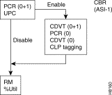
Table 5-4: ASI-1, ATM Connection Parameters, CBR
| Parameter 1 | Range | Default | Definition 2 |
|---|---|---|---|
| UPC | enable/disable | enable | Usage Parameter Control, controls both buckets. |
| RM | enable/disable | disable | Resources Direction |
| Ingress Policing | |||
| PCR (0+1) | 10-96000 T3 ten-80000 E3 | x | Height Prison cell rate for CLP(0+1) cells |
| CDVT (0+ane) | 1-250000 | thou | Jail cell Delay Variation Tolerance for CLP=0+1 cells |
| PCR (0) | 10-96000 | PCR(0+one) | Peak Cell rate for CLP=0 cells, must be <= PCR(0+i) |
| CDVT (0) | 1-250000 | CDVT(0+1) | Jail cell Delay Variation Tolerance for CLP=0 cells |
| CLP | enable/disable | enable | Prison cell Loss Priority Tagging |
| General Connection Parameters | |||
| % Util | ane-100% | 100% | BW allocation is PCR(0+1) * %Util |
1 The notation 0,i, and 0+i refers to the types of cell being specified: cells with CLP set to 0, CLP gear up to 1, or both types of cells. For example, CDVT(0), CDVT(1), and CDVT(0+i), respectively
2 (Units in cells or cells per 2d unless otherwise indicated)
CBR Connection Parameters
(Parameters are listed alphabetically.)
CDVT (Prison cell Delay Variation Tolerance)—For CBR and VBR connections, CDVT can be configured to allow the connexion to exceed PCR for some flow of fourth dimension.
- The PCR specifies a strict spacing between cells. For instance, a PCR of 48,000 cells per 2d ways that there must be an interval of at to the lowest degree 20.8 usecs between the arrival of one cell and the next cell.
- Configuring CDVT = 0, means that a cell arriving less than 20.eight usec afterward the previous jail cell is considered non-compliant. Configuring a non-zero CDVT allows cells to arrive sooner, yet still be considered compliant.
CLP (Jail cell Loss Priority Enable)—Enables/disables Cell Loss Priority tagging for the connexion.
- Responding "disable" to this prompt disables tagging with a CLP bit of non-compliant cells at leaky bucket 2. Non-compliant cells are dropped.
- Responding "enable" to this prompt directs the system to admit not-compliant cells, but to tag them with a CLP bit. (In any event, the non-compliant prison cell rate at Leaky Bucket 2 can not exceed the PCR of leaky bucket 1).
PCR (Peak Prison cell Rate)—This is the maximum rate at which cells are allowed into the network.
%util (Per centum Utilization)—%util is expressed as a per centum of PCR. Equally each PVC is routed, bandwidth on the private network trunks is "consumed" by a value equal to PCR times the %util.
- Configuring %util to 100%, ensures that each CBR connexion is able to transmit at its PCR even when the network is fully congested.
- By configuring %util to be less than 100%, the user can over-subscribe the bandwidth on network trunks, thus providing a level of statistical multiplexing. However, to do so voids the PCR "contract" that the user has requested.
RM (Resource Management)—For external management. When an RM jail cell is received the ASI generates a statistic and sends the cell on its way into the network, unless it is an ABR or ATFST connection. For ABR and ATFST connections only, if the RM pick is enabled, when the queue depth exceeds the EFCI threshold, an RM indication is sent back out the port.
UPC (Usage Parameter Control)—Enable or disable policing. With UPC disabled, all cells for a PVC are admitted regardless of charge per unit.
CBR Dual-Leaky Bucket Case
CBR traffic is expected to be at a constant bit rate, have depression jitter, and is configured for a constant rate equal to Top Cell Rate (PCR). The connection is expected to be always at peak charge per unit.
When a connection is added, a VPI.VCI address is assigned, and the UPC parameters are configured for the connection. For each prison cell in an ATM stream seeking admission to the network, the VPI.VCI addresses are verified and each cell is checked for compliance with the UPC parameters as shown in Figure five-four. The CBR cells are not enqueued, but are candy by the policing function and so sent to the network unless discarded.
For CBR, traffic policing is based on:
- Bucket 1
- PCR(0+1), Peak Cell Rate
- CDVT(0+1), Prison cell Delay Variation
- Bucket 2
- PCR(0)
- CDVT(0)
Figure 5-iv: CBR Connexion UPC Overview
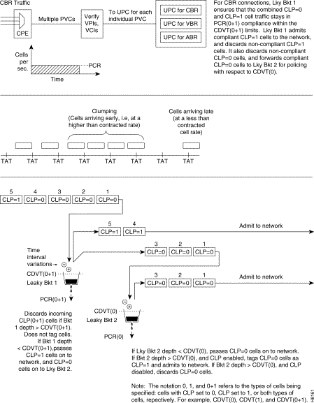
Leaky bucket 1 polices the PCR compliance of all cells seeking access to the network, both those with CLP = 0 and those with CLP =i (Effigy v-iv). Cells seeking admission to the network with CLP set equal to 1 may have either encountered congestion forth the user'due south network or may take lower importance to the user and have been designated every bit eligible for discard in the example congestion is encountered. If the saucepan depth in the first saucepan exceeds CDVT (0+1) it discards all cells seeking admission. It does not tag cells. If leaky bucket i is not full, all cells with CLP =1 are admitted to the network bypassing leaky bucket 2, and all cells with CLP=0 are sent on to leaky bucket 2.
Leaky bucket 2 polices all cells with CLP = 0 that accept been passed by leaky bucket i. Leaky bucket ii tin either tag or discard cells. Cells found out of compliance past leaky bucket two are either discarded or tagged as CLP=1. The purpose of leaky bucket 2 for CBR connections is to provide the option of a CDVT(0) limit for CLP=0 cells which may exist lower but cannot exceed the CDVT(0+1) of leaky saucepan ane. Typically, CDVT(0) is set equal to CDVT(0+1).
Figure 5-five shows a CBR connexion policing example where the CDVT depth of both the dual leaky buckets is less than the limit.
Figure 5-five: CBR Connexion with both Buckets Compliant
Effigy 5-6 shows a CBR connection policing case where the CDVT(0) of Leaky Bucket 2 is exceeded and the CLP=0 cells that are non-compliant are tagged as CLP=1 by Leaky Saucepan 2.
Figure 5-6: CBR Connexion, with Bucket 2 Tagging non-Compliant Cells
Figure 5-seven shows a CBR connexion policing example where the CDVT(0) of leaky saucepan 2 is exceeded and the CLP=0 cells are discarded.
Figure five-7: CBR Connection, with Bucket 2 Discarding non-Compliant Cells
Effigy 5-8 shows a CBR connexion policing instance where the CDVT(0+1) of leaky saucepan 1 is exceeded and non-compliant cells are discarded. Leaky bucket i just discards cells; it does not tag them
Effigy 5-8: CBR Connection, with Bucket ane Discarding non-Compliant Cells
VBR Connections, ASI-1 (T3/E3)
Variable Fleck Charge per unit (VBR) connections are those expected to vary over time, with bursts of information occurring up to peak rates. Typical of these connections are transactions, image transfers, file transfers, interactive video, etc.
A quality of service QoS contract for VBR would include a guaranteed minimum charge per unit, referred to equally the sustainable jail cell rate (SCR), a Peak Cell Rate (PCR) which is the maximum rate at which data is allowed to burst, and a Maximum Outburst Size (MBS) which is the maximum number of cells allowed to burst above the sustainable jail cell rate for a short time.
The parameters applicable to a VBR connection are shown in Figure 5-9. The flow nautical chart denotes the parameters for a connection for which the connection blazon, VPI.VCI, slot, and port have already been specified.
A summary of the parameters applicable to a VBR connection is provided in Table 5-5.
Figure 5-9: ASI-i, VBR/ATFR Connection Prompting for a Specified VPI.VCI
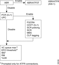
Table five-v: ASI-one, ATM Connection Parameters, VBR and ATF
| Parameter one | Range | Default | Definition ii |
|---|---|---|---|
| abr | enable/disable | disable | Disable configures a vbr connection, enable configures an abr connection (See abr clarification and table.) |
| UPC | enable/disable | enable | Usage Parameter Control |
| RM | enable/disable | disable | Resource Management |
| Ingress Policing | |||
| PCR (0+1) | seven-96000 T3 vii-80000 E3 7-5333 ATFR | 10 | Peak Cell rate for CLP=0+1 cells |
| FGCRA | enable/disable | disable | Frame Based Generic Cell Rate Algorithm (enable/disable) |
| CDVT (0+1) | one-250000 | 1000 10000 (ATFR) | Cell Filibuster Variation Tolerance for CLP=0+1 cells (in µsecs) |
| SCR Policing | 1-3 | i | ane. CLP(0), 2. CLP(0+i), three. Off |
| SCR | 7-96000 T3 vii-80000 E3 vii-5333 ATFR | PCR (0+i) | Sustained Cell Rate |
| MBS | 1-24000 | one thousand | Maximum Burst Size |
| CLP | enable/disable | enable | Cell Loss Priority Tagging |
| General Connection Parameter | |||
| % Util | 1-100% | The minimum of: 100% or 120%*SCR/PCR | BW allocation is PCR(0+ane) * %Util |
| Prompted for ATFR Connections Only | |||
| VC Q Max | 1-1366 | 1366 | Specifies Maximum ingress queue depth for frame relay side of ATFR connection |
| EFCI | 1-100% | 100 | Explicit Forward Congestion Indication setting threshold (% of VC Q Depth) for frame relay side of ATFR connectedness. |
| IBS | 1-107 cells | 1 | Initial burst size for frame relay side of ATFR connection |
1 The notation 0,one, and 0+ane refers to the types of cell being specified: cells with CLP set to 0, CLP prepare to one, or both types of cells. For example, CDVT(0), CDVT(1), and CDVT(0+1), respectively.
2 (Units in cells or cells per second unless otherwise indicated)
VBR Connection Parameter Descriptions
(Parameters are listed alphabetically.)
CDVT(0+1) (Cell Delay Variation Tolerance)—For CBR and VBR, CDVT can be configured to permit the connection to exceed PCR for some period of time.
- CDVT is expressed in µsecs. Information technology is the maximum time period for accumulated violations of cell-arrival time parameters.
CLP (Cell Loss Priority)—Enables/disables Cell Loss Priority tagging for the connectedness for leaky bucket 2. If not enabled and the BT + CDVT limit of leaky bucket ii is exceeded, cells will be discarded.
- Responding "disable" to this prompt disables tagging with a CLP flake of non-compliant cells at leaky saucepan 2. Not-compliant cells are dropped.
- Responding "enable" to this prompt directs the organization to admit non-compliant cells, only to tag them with a CLP bit. (In any consequence the non-compliant prison cell rate at leaky saucepan two tin can non exceed the PCR of leaky saucepan 1)
FGCRA (Frame Based Generic Prison cell Charge per unit Algorithm)—an ASI feature that controls access of cells to the network. Information technology is a StrataCom enhancement of the ATM-UNI standard Generic Jail cell Rate Algorithm. Selecting FGCRA allows an unabridged frame to be discarded if whatever of its cells are non-compliant, rather than transmitting a partial frame over the network. Enabling FGCRA forces a UPC frame-based cell discard or tagging. For example, if one prison cell of a frame is discarded or tagged, then all remaining cells are discarded or tagged, except for the End of Frame (EOF) cell.
MBS (Maximum Burst Size)—the maximum number of cells between SCR and PCR (measured over a given period) that can be received at the PCR and be considered compliant.
PCR(0+1) (Superlative Cell Rate)—This is the maximum rate that cells are allowed into the network.
%util (Percent Utilization)
- For VBR PVCs, %util is expressed as a percentage of PCR. As each PVC is routed, bandwidth on the individual network trunks is "consumed" by a value equal to PCR times the %util.
- Configuring %util to 100%, ensures that each VBR connectedness is able to transmit at its PCR even when the network is fully congested.
- Past configuring %util to exist less than 100%, the user can over-subscribe the bandwidth on network trunks, thus providing a level of statistical multiplexing. However, to practice so voids the PCR "contract" that the user has requested.
RM (Resource Direction)—For external management. When an RM cell is received the ASI generates a statistic and sends the cell on its style into the network, unless it is an ABR or ATFST connection. For ABR and ATFST connections only, if the RM pick is enabled, when the queue depth exceeds the EFCI threshold, an RM indication is sent dorsum out the port.
SCR (Sustainable Cell Rate)—Cells received at a rate greater than SCR are either tagged or dropped.
SCR Policing—Selects the type of policing performed for sustained cell rate and maximum outburst size compliance. There are three choices;
- 1. CLP = (0), all cells with CLP=0 that pass the first leaky bucket are policed for compliance for sustained prison cell rate and burst size. Cells with CLP=1 that pass the first leaky saucepan are applied directly to the network.
- 2. CLP = (0+i), all cells with CLP=0+1 that pass the first leaky saucepan are policed for compliance for sustained cell rate and flare-up size.
- three. Off, no policing is performed on sustained cell rate and flare-up size and the PVC is allowed to apply cells up to the height rate (PCR).
UPC (Usage Parameter Command)—Enable or disable policing. With UPC disabled, all cells for a PVC are admitted regardless of rate.
VBR Dual-Leaky Saucepan Example
The contract for a variable scrap rate connection is ready upwardly based on an agreed upon sustained cell charge per unit (SCR) with allowance for occasional data bursts at a Peak Prison cell Rate (PCR) every bit specified by maximum burst size MBS.
When a connection is added, a VPI.VCI accost is assigned, and UPC parameters are configured for the connection. For each cell in an ATM stream, the VPI.VCI addresses are verified and each cell is checked for compliance with the UPC parameters equally shown in Figure five-10.
The VBR cells are not enqueued, but are processed by the policing function and so sent to the network unless discarded.
The parameters associated with a VBR connection are:
- Leaky bucket 1, PCR and CDVT
- Leaky bucket 2, SCR, CDVT, and MBS
Figure 5-10: VBR Connection UPC Overview
Leaky Bucket 1
Leaky bucket 1 polices for PCR compliance of all cells seeking access to the network, both those with CLP = 0 and those with CLP =1. For instance, cells seeking admission to the network with CLP ready equal to ane may take either encountered congestion along the user's network or may have lower importance to the user and take been designated as eligible for discard in the case congestion is encountered. If the saucepan depth in the showtime bucket exceeds CDVT (0+one), information technology discards all cells seeking admission. It does not tag cells. If leaky saucepan 1 is not full, all cells with CLP=0 are sent to leaky bucket ii, and all cell with CLP =i are either directly admitted to the network or sent to leaky saucepan 2, depending on user selection.
Leaky Bucket two
For VBR connections, the purpose of leaky bucket 2 is to police the cells passed from leaky bucket 1 for conformance with maximum burst size MBS as specified by BT and for compliance with the SCR sustained cell charge per unit. The type of cells passed to leaky saucepan ii depend on how SCR is configured, either none, CLP(0) cells, or CLP(0+ane) cells.
- For SCR= off, leaky bucket 2 sees no traffic.
- For SCR = CLP(0), the CLP(0) cells are admitted to the network if compliant with BT + CDVT(0+1) of leaky bucket two. If not compliant, cells may either exist tagged or discarded per user enabling or disabling of CLP tagging, respectively.
- For SCR = CLP(0+1), the CLP(0) and CLP(one) cells are admitted to the network if compliant with CDVT(0+1) of leaky bucket 2. If not compliant, the cells are discarded. There is no tagging option.
Examples
Effigy five-eleven shows a VBR connection policing example, with the SCR parameter set to Off, and leaky bucket 1 compliant.
Figure 5-11: VBR Connection, SCR Off, Leaky Bucket 1 Compliant
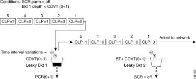
Figure 5-12 shows a VBR connection policing example, with the SCR parameter set to Off, and leaky bucket 1 not-compliant which indicates that the connectedness has exceeded the PCR for a long enough interval to exceed the CDVT (0+1) limit. Not-compliant cells with respect to leaky bucket 1 are discarded.
Figure 5-12: VBR Connectedness, SCR Off, Leaky Bucket 1 Not-Compliant
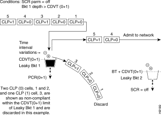
Figure v-13 shows a VBR connection policing example, with SCR = CLP(0), and both buckets compliant. Leaky saucepan two is policing the CLP(0) cell stream for conformance with maximum flare-up size MBS (as specified by BT), and for compliance with the SCR sustained cell rate.
Figure five-13: VBR Connection,SCR=CLP(0), with Buckets1 and 2 Compliant
Effigy five-14 shows a VBR connectedness policing case, with SCR ready to CLP=0, and leaky saucepan two non-compliant. Leaky bucket ii is shown policing the CLP(0) cell stream for conformance with maximum burst size MBS (every bit specified by BT), and for compliance with SCR (sustained cell rate). In this case, CLP tagging is not enabled, and then the cells that have exceeded the BT + CDVT(0) limit are discarded. In this case, either the sustained cell rate could have been exceeded for an excessive interval, or a data flare-up could take exceeded the maximum allowed burst size.
Effigy 5-14: VBR Connection, Leaky Bucket 2 Discarding CLP (0) Cells
Figure 5-15 shows a VBR connection policing example, with SCR = CLP(0+ane), and both buckets compliant. Leaky bucket 1 is policing the CLP (0+one) cell stream for conformance with the PCR limit. Leaky bucket 2 is policing the CLP (0+1) cell stream for conformance with maximum burst size MBS (equally specified by BT), and for compliance with SCR sustained jail cell rate.
Effigy five-15: VBR Connection, SCR=CLP(0+1), with Buckets 1 and 2 Compliant
Effigy 5-16 shows a VBR connection policing instance, with SCR set to CLP(0+1), and Leaky bucket 2 shown equally not-compliant. Leaky bucket 2 is shown policing the CLP=0 cell stream for conformance with maximum burst size MBS (as specified by BT), and for compliance with SCR sustained cell charge per unit. For the SCR option of CLP(0+1), CLP tagging is not an choice, so the cells that take exceeded the BT + CDVT limit are discarded. In this example, either the sustained cell rate was exceeded for an excessive interval, or a data burst occurred greater than the maximum immune burst size.
Figure 5-16: VBR Connexion, with Leaky Bucket 2 Discarding CLP(0+ane) Cells
ABR Connections, ASI-1 (T3/E3)
Bachelor Scrap Rate (ABR) connections are policed the same as the VBR connections, simply use the ForeSight choice to have advantage of unused bandwidth when it is available. The dual leaky bucket GCRA algorithm functions are the same as for VBR connections, except that instead of the cells being immediately admitted to the network, they outset go through the IBS (Initial Outburst Size) role and then to the ABR queue.
The parameters applicable to an ABR connection are shown in Figure 5-17. The flow chart denotes the parameters for a connection for which the connection type, VPI.VCI, slot, and port have already been specified.
A summary of the parameters applicable to an ABR connection are listed in Table v-6.
Figure 5-17: ASI-1, ABR/ATFST Connection Prompting for a Specified VPI.VCI
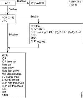
Tabular array 5-six: ASI-1, ATM Connexion Parameters, ABR and ATFST
| Parameter 1 | Range | Default | Definition two |
|---|---|---|---|
| abr | enable/disable | enable | Enable configures an abr connection, disable configures a vbr connexion (See vbr description and table.) |
| UPC | enable/disable | enable | Usage Parameter Control |
| RM | enable/disable | disable | Resource Management |
| Ingress Policing | |||
| PCR (0+i) | 7-96000 T3 7-80000 E3 7-5333 ATFST | 10 | Superlative Cell charge per unit for CLP=0+1 cells |
| FGCRA | enable/disable | disable | Frame Based Generic Jail cell Rate Algorithm) |
| CDVT (0+1) | one-250000 | 1000 10000 (ATFST) | Prison cell Delay Variation Tolerance for CLP=0+1 cells (in µsecs) |
| SCR Policing | ane-3 | 1 | i. CLP(0), 2. CLP(0+ane), 3. Off |
| SCR | 7-96000 T3 seven-80000 E3 7-5333 ATFST | PCR(0+one) | Sustained Cell Rate |
| MBS | i-24000 | grand | Maximum Burst Size |
| CLP | enable/disable | enable | Jail cell Loss Priority Tagging for CLP=0 |
| Ingress Queue Threshold | |||
| IBS | 0 -24000 (ABR) 1-107 (ATFST) | 0 (ABR) 1 (ATFST) | Initial Burst Size |
| EFCI | 1-100% | 100% | Explicit Forward Congestion Indication setting threshold (% of VC Q Depth) |
| CLP Howdy | 1-100% | 90% | Jail cell Loss Priority High Threshold |
| CLP Lo | ane-100% | 80% | Cell Loss Priority Low Threshold |
| VC Q depth | 1-64000 (ABR) ane-1366 (ATFST) | 16000 (ABR) 1366 (ATFST) | PVC ingress queue depth) depth in bytes for ATFST |
| ForeSight | |||
| ICR | 0-96000 T3 0-80000 E3 seven-5333 ATFST | Max of: (MCR or PCR(0+1)/ten) | Initial Cell Rate |
| ICR TO | one-255 | x | Initial Jail cell Rate Time Out (seconds) |
| Rate Upward | 10-96000 T3 10-80000 E3 | Max of: (10% of MCR, or 2000) | Rate Up increase. Note: This is in cells per second per aligning |
| Charge per unit Downwardly | one-100 | 87% | Rate Down Increment |
| Rate Fast Down | 1-100 | 50% | Rate Fast Down lowers rate in large increments |
| Min Adjust | 20-250 | twoscore | The interval at which charge per unit adjustments are made (ms) |
| General Connection Parameters | |||
| MCR | 0-96000 T3 0-80000 E3 7-5333 ATFST | 0 0 x | Minimum Prison cell Charge per unit |
| % Util | 1 to 100% | MCR/PCR | % Utilization, bandwidth allotment is: MCR * %util |
1 The notation 0,one, and 0+ane refers to the types of prison cell being specified: cells with CLP set to 0, CLP set to 1, or both types of cells. For example, CDVT(0), CDVT(ane), and CDVT(0+i), respectively
ii (Units in cells or cells per 2d unless otherwise indicated)
ABR Connectedness Parameter Descriptions
(Parameters are listed alphabetically.)
CDVT(0+1) (Cell Delay Variation Tolerance)—For CBR and VBR, CDVT can be configured to permit the connection to exceed PCR for some period of fourth dimension.
- ABR: CDVT is expressed in µsecs. It is the maximum time menses for accumulated violations of prison cell-arrival time parameters.
CLP (Cell Loss Priority)—Enables/disables Cell Loss Priority tagging for the connection for leaky bucket 2. If not enabled and the BT + CDVT limit of leaky bucket 2 is exceeded, cells will be discarded.
- Responding "disable" to this prompt disables tagging with a CLP bit of non-compliant cells at leaky saucepan ii. Non-compliant cells are dropped.
- Responding "enable" to this prompt directs the organisation to admit non-compliant cells, but to tag them with a CLP bit. (In whatever issue the non-compliant cell rate at leaky saucepan 2 tin can not exceed the PCR of leaky bucket 1)
CLP Low Threshold/CLP High Threshold—The CLP Low and High thresholds are configured as a percentage of the VC Queue depth (ingress queue for ABR connections). Once the queue exceeds the CLP Loftier Threshold, CLP=1 cells are non admitted until the queue depth falls below the CLP Low Threshold.
Tabular array 5-vii lists the conditions under which ABR cells are either admitted to the ingress queue or are discarded, depending on the whether the prison cell has its CLP bit set equal to 0 or one, and on the status of the queue depth with respect to CLP High and Low thresholds, or on whether the queue is full.
Table 5-seven: ASI-1, Cell Access to an ABR PVC's Ingress Queue
| Queue Status | Incoming Jail cell with CLP = 0 | Incoming Cell with CLP = ane |
|---|---|---|
| VcQ depth < CLP Low | Admit Cell | Admit Cell |
| CLP Low < VcQ depth < CLP High | Admit Prison cell | Acknowledge Cell |
| CLP Low < VcQ depth < CLP High | Admit Jail cell | Discard Jail cell |
| VcQ depth > CLP Loftier | Admit Jail cell | Discard Cell |
| VcQ is full (PVC queue depth exceeded) | Discard Prison cell | Discard Cell |
EFCI (Explicit Forward Congestion Indication)—a threshold setting configured every bit a percentage of VCQ depth. If the VCQ depth exceeds the EFCI threshold, cells are tagged with an EFCI bit which indicates congestion in the network. The ForeSight mechanism monitors cells for this bit at the egress ASI card and provides feedback aligning information to the ingress ASI bill of fare to adjust the charge per unit of jail cell access to the network, accordingly.
Fast Downward—is the rate at which the connection is ramped downward in big increments toward the MCR when severe congestion occurs forth its road. Fast Downwards is expressed as a percentage of the current rate.
FGCRA (Frame Based Generic Jail cell Rate Algorithm)—an ASI feature that controls admission of cells to the network. It is a StrataCom enhancement of the ATM-UNI standard Generic Cell Charge per unit Algorithm. Selecting FGCRA allows an entire frame to be discarded if any of its cells are non-compliant, rather than transmitting a partial frame over the network. Enabling FGCRA forces a UPC frame-based cell discard or tagging. For example, if one cell of a frame is discarded or tagged, then all remaining cells are discarded or tagged, except for the End of Frame (EOF) prison cell.
IBS (Initial Burst Size)—
- If a cell is received and the connection has been either quiescent or transmitting at a very depression rate, the traffic policing module admits the cell as being compliant and signals the VC Queue director to immediately transmit a jail cell from the queue to the network.
- In a sense, as long as the connection has not exceeded IBS, cells are immediately admitted to the network every bit though the connection were CBR. Nevertheless, once in the network, the cells travel through dedicated ABR queues.
ICR (Initial Cell Rate)—Depending on network congestion, cells are served from the VC Queue at a rate varying between MCR and PCR. If a PVC has been quiescent for a configurable amount on time (ICR TO), its queue will initially be served at this charge per unit. The rate will afterward adapt upwards or down nether the command of the ForeSight Charge per unit Control Algorithm.
ICR TO (Initial Prison cell Rate Time Out)—ICR TO defines the menstruum of inactivity before a PVC is reset to its ICR. Ordinarily a PVC is served at a rate based on feedback received via ForeSight. Still, if a PVC has been quiescent for some time, it is not possible to make up one's mind if this PVC would experience congestion at the beginning of its next burst. Therefore, if the ICR TO has expired, the PVC is reset to its ICR. If the timeout has not expired, the PVC will resume transmitting at its previous rate.
VC Q Depth—
- Defines the maximum number of cells that may be queued (pending admittance to the network) for a PVC.
- The ASI-1 card has a full of 64,000 cells of ingress buffer.
- This is shared by all PVCs on all ports of the carte du jour.
Although private PVC queues may non exceed 64,000 cells, the user may configure queues that full more than 64,000, in essence "oversubscribing" the queue infinite.
Configurable Connexion Parameters, ASI-155
There are a number of parameters associated with ATM connections and ATM ports that are user-configurable. The following paragraphs describe the parameters used to configure ATM connections on the ASI-155, including the single leaky bucket GCRA parameters.
UPC Policing
The ASI-155 employs a single leaky saucepan GCRA machinery for policing cell streams seeking entrance to the network.) Each pvc (VPC.VCC) is policed separately, providing firewalling between connections, and assuring that each connection uses only a fair share of network bandwidth
Policing for ASI-155 connections is implemented with a unmarried leaky saucepan using a GCRA (Generic Rate Algorithm) divers past ii parameters:
- Charge per unit (where I, expected arrival interval is divers as 1/Charge per unit)
- Deviation (L)
CBR Connections, ASI-155
Constant bit rate (CBR) connections are those that cannot tolerate delays of any significance. These connections include voice and video, etc.
A quality of service QoS contract for CBR would include depression filibuster, and a constant input rate. All cells volition be served then long as the connection does non exceed its constant rate. A CBR connection is specified to be transmitted beyond the network at a stock-still rate. This rate is specified as PCR, peak jail cell rate. The rate of the connection is allowed to vary slightly within the limits specified by CDVT (prison cell delay variation tolerance).
The parameters applicable to a CBR connexion are shown in Figure five-xviii. The flowchart denotes the parameters for a connection for which the connection type, VPI.VCI, slot, and port have already been specified.
A summary of the parameters applicable to a CBR connectedness are listed in Table 5-8.
Effigy 5-18: ASI-155, CBR Connection Prompting for a Specified VPI.VCI
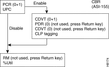
Table five-8:
| Parameter | Range | Default | Definition 1 |
|---|---|---|---|
| UP | enable/disable | enable | Usage Parameter Control, enables or disables both buckets. |
| RM | non used | disabled | Non used, press Return key |
| Ingress Policing | |||
| PCR (0+1) | 7-353208 | 10 | Peak Cell charge per unit for CLP=0+i cells |
| CDVT (0+1) | 1-1000 | 1000 | Prison cell Delay Variation Tolerance for CLP=0+1 cells (in µsecs) |
| PCR (0) | not used | non used | Not used, press Return primal |
| CDVT (0) | not used | CDVT(0+1) | Not used, press Return key |
| CLP | enable/disable | enable | Prison cell Loss Priority Tagging |
| General Connection Parameters | |||
| % Util | 1-100% | 100% | BW allocation is PCR(0+1) * %Util |
ane Units in cells or cells per second unless otherwise indicated.
CBR Connectedness Parameters
(Parameters are listed alphabetically.)
CDVT (Cell Delay Variation Tolerance)—For CBR and VBR connections, CDVT tin can be configured to allow the connection to exceed PCR for some menstruum of time.
- CBR: The PCR specifies a strict spacing between cells. For example, a PCR of 48,000 cells per 2nd means that there must be an interval of at least xx.viii usecs between the inflow of one cell and the next jail cell.
- Configuring CDVT = 0, ways that a cell arriving less than 20.eight usec subsequently the previous cell is considered not-compliant. Configuring a non-zero CDVT allows cells to arrive sooner, even so still be considered compliant.
CLP (Cell Loss Priority Enable)—Enables/disables Cell Loss Priority tagging for the connection.
- Responding "disable" to this prompt disables tagging with a CLP bit of not-compliant cells. Non-compliant cells are dropped.
- Responding "enable" to this prompt directs the arrangement to admit not-compliant cells, simply to tag them with a CLP bit.
PCR (Peak Prison cell Rate)—This is the maximum rate at which cells are allowed into the network
%util (Per centum Utilization)—
- For CBR PVCs, %util is expressed as a percentage of PCR. As each PVC is routed, bandwidth on the individual network trunks is "consumed" by a value equal to PCR times the %util.
- Configuring %util to 100%, ensures that each CBR connection is able to transmit at its PCR even when the network is fully congested.
- By configuring %util to be less than 100%, the user tin can over-subscribe the bandwidth on network trunks, thus providing a level of statistical multiplexing. Still, to do so voids the PCR "contract" that the user has requested.
RM (Resource Direction)—Not used.
UPC (Usage Parameter Control)—Enable or disable policing. With UPC disabled, all cells for a pvc are admitted regardless of rate.
VBR Connections, ASI-155
Variable Flake Rate (VBR) connections are those expected to vary over time, with bursts of data occurring up to peak rates. Typical of these connections are transactions, prototype transfers, file transfers, interactive video, etc.
A quality of service QoS contract for VBR would include a guaranteed minimum charge per unit, referred to as the sustainable jail cell rate (SCR), a Peak Cell Rate (PCR) which is the maximum rate at which information is allowed to burst, and a Maximum Outburst Size (MBS) which is the maximum number of cells immune to burst above the sustainable cell rate for a short time.
The parameters applicative to a VBR connectedness are shown in Figure v-xix. The flowchart denotes the parameters for a connexion for which the connection blazon, VPI.VCI, slot, and port take already been specified.
A summary of the parameters applicable to a VBR connection are listed in Table 5-ix.
Figure v-19: ASI-155, VBR/ATFR Connection Prompting for a Specified VPI.VCI
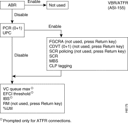
Table five-9: ASI-155, ATM Connexion Parameters, VBR and ATFR
| Parameter 1 | Range | Default | Definition 2 |
|---|---|---|---|
| abr | enable/disable | disable | Disable configures a vbr connection, enable which configures an abr connexion is non used. |
| UPC | enable/disable | enable | Usage Parameter Control |
| RM | not used | disabled | Non used, press Return fundamental |
| Ingress Policing | |||
| PCR (0+1) | vii-353208 | 10 | Peak Cell charge per unit for CLP=0+1 cells |
| FGCRA | non used | disabled | Not used, press Return fundamental |
| CDVT (0+1) | not used | not used | Not used, press Render key |
| SCR Policing | non used | not used | Not used, printing Return fundamental |
| SCR | seven-353208 | PCR (0+1) | Sustained Cell Charge per unit |
| MBS | 10-grand | thousand | Maximum Outburst Size |
| CLP | enable/disable | enable | Cell Loss Priority Tagging |
| Full general Connexion Parameter | |||
| % Util | ane-100% | The minimum of: 100% or 120%*SCR/PCR | BW allocation is PCR(0+one) * %Util |
| Prompted for ATFR Connections Only | |||
| VC Q Max | one-1366 | 1366 | Specifies Maximum ingress queue depth for frame relay side of ATFR connection. For VBR connection, non used, press Return key. |
| EFCI | one-100% | 100 | Explicit Frontward Congestion Indication setting threshold (% of VC Q Depth) for frame relay side of ATFR connection. For VBR connection, non used, press Return fundamental. |
| IBS | 1-107 cells | i | Initial burst size for frame relay side of ATFR connectedness. For VBR connection, non used, printing Return key. |
i The notation 0,1, and 0+i refers to the types of jail cell being specified: cells with CLP ready to 0, CLP set to i, or both types of cells. For example, CDVT(0), CDVT(ane), and CDVT(0+1), respectively.)
2 (Units in cells or cells per second unless otherwise indicated)
VBR Connection Parameter Descriptions
(Parameters are listed in alphabetical order.)
CDVT(0+1) —(Not used)
CLP (Cell Loss Priority)—Enables/disables Cell Loss Priority tagging for the connexion:
- Responding "disable" to this prompt disables tagging of non-compliant cells with a CLP fleck. Not-compliant cells are dropped.
- Responding "enable" to this prompt directs the system to admit non-compliant cells, but to tag them with a CLP bit.
FGCRA (Frame Based Generic Cell Rate Algorithm)—is an ASI characteristic that controls access of cells to the network. It is a StrataCom enhancement of the ATM-UNI standard Generic Cell Rate Algorithm. Enabling FGCRA forces a UPC frame-based jail cell dicard or tagging. For example, if one prison cell of a frame is discarded or tagged, then all remaining cells are discarded or tagged, except for the Terminate of Frame (EOF) cell.
MBS (Maximum Burst Size)—is the maximum number of cells (betwixt SCR and PCR measured over a given period) that can be received at the PCR and be considered compliant.
PCR(0+1) (Peak Prison cell Charge per unit)—This is the maximum rate at which cells are immune into the network.
%util (Pct Utilization)
- For VBR PVCs, %util is expressed equally a percentage of PCR. Every bit each PVC is routed, bandwidth on the private network trunks is "consumed" by a value equal to PCR times the %util.
- Configuring %util to 100%, ensures that each VBR connectedness is able to transmit at its PCR even when the network is fully congested.
- By configuring %util to exist less than 100%, the user can over-subscribe the bandwidth on network trunks, thus providing a level of statistical multiplexing. However, to practice so voids the PCR "contract" that the user has requested.
RM (Resource Management)—Not used.
SCR (Sustainable Cell Rate)—Cells received at a rate greater than SCR are either tagged or dropped.
SCR Policing—Not used.
Port Statistics
Port Statistics for the ASI-1
The port stats for the ASI-1 include:
- Rx Port Cells
- Rx Port Cells with CLP
- Rx Port Cells with EFCI
- Tx Port Cells
- Tx Port Cells with CLP
- Tx Port Cells with EFCI
- Cells with Unknown Address
- Last Unknown Address
- Tx Payload Error Count
- Tx Header Error Discard
Port Statistics for the ASI-155
Per port ATM Layer statistics:
- Number of cells received at the CIE with CLP=1
- Number of cells transmitted to the network (BIF Tx FIFO)
- Number of cells discarded due to unconfigured VPI.VCI
- Number of cells discarded due to BFrame=0 (BF field in header = 0)
- Number of cells transmitted out of the port with CLP=1
Number of cells transmitted out of the port:
- Number of cells discarded due to BFrame header parity error or due to BIP-16 error on the BFrame and STI headers
- Number of cells with data payload parity mistake
- Number of cells transmitted with CLP=1
- Number of cells transmitted with EFCI=i
Per egress queue (for each port) ATM layer statistics:
- Number of cells discarded due to egress queue beingness full
- Number of cells discarded due to egress queue existence disabled
- Number of cells transmitted
- Number of cells transmitted with CLP=one
LMI Statistics
- Status Rx/Tx
- Update Status Rx/Tx
- Condition Enq Rx/Tx
- Status Ack Rx/Tx
- Invalid PDU Rx
- Invalid PDU Len Rx
- Unknown PDU Rx
- Invalid I.E. Rx
- Invalid Transaction
ILMI Statistics
- Become Request Rx/Tx
- Get Response Rx/Tx
- Go Nest Req Rx/Tx
- Trap Rx/Tx
- Set Request Rx/Tx
- Unknown PDU Rx
Connection Monitoring, OAM Cells
ATM connections discover and laissez passer Alarm Data Signal (AIS) and Remote Defect Indication (RDI) {formerly Far End Receive Failure (FERF)} indications transparently. These alarm indications are carried by ATM Operations and Maintenance (OAM) cells. AIS may be generated by the user device or a foreign ATM network in response to upstream failures. RDI is transmitted in the opposite direction when an AIS is detected.
Since these signals are required to laissez passer finish-to-cease, the OAM cells are queued like normal cells. AIS detection on a PVC is reported by a node to StrataView Plus. AIS may also be generated by a BPX node in response to a PVC segment failure inside the StrataCom network.
OAM Cells supported by the ASI-1
OAM Cells supported:
- End-to-terminate OAM flows and end-to-end loopback per ATM Forum UNI v3.1
- External segment flows consisting of segment loopback cells per ATM Forum UNI v3.1
OAM Cells supported past the ASI-155
OAM Cells supported:
- Cease-to-end OAM flows and stop-to-end loopback per ATM Forum UNI v3.1
- External segment flows consisting of segment loopback cells per ATM Forum UNI v3.1
Concrete Layer
ASI-1 Physical Layer Line Alarms
DS3
- Loss of Indicate (LOS)
- Loss of Frame (LOF)
- Line Warning Indication Indicate (AIS)
- Remote Defect Indication (RDI)
- PLCP Loss of Frame (PLCP-LOF)
- PLCP-Remote Defect Indication (PLCP-RDI)
E3
- Loss of Point (LOS)
- Loss of Frame (LOF)
- Loss of Cell Delineation (LOC)
- Line Alarm Indication Indicate (AIS)
- Remote Defect Indication (RDI)
ASI-i DS3 Statistics
Table 5-10 lists ASI-one DS3 Statistics.
Table v-10: ASI-ane DS3 Statistics
| Line Lawmaking Violation | P-Bit Code Violation | C-chip Lawmaking Violation | PLCP | |
|---|---|---|---|---|
| About End | Far Emd | |||
| LCV | PCB | CCV | BIP-viii | FEBE |
| LES | Human foot | CES | BIP-8ES | FEBE ES |
| LSES | PSES | CSES | BIP-SES | FEBE SES |
| UAS | PLCP-UAS | |||
ASI-i E3 Statistics
Table v-eleven lists ASI-ane E3 Statistics.
Table 5-xi: ASI-one E3 Statistics
| Line Code Violation | PLCP | |
|---|---|---|
| Near End | Far Emd | |
| LCV | BIP-8 | FEBE |
| LES | BIP-8ES | FEBE ES |
| LSES | BIP-SES | FEBE SES |
ASI-155 Physical Layer Alarms
Alarms and performance monitoring supported as per Bellcore GR-253-Core
- Loss of Indicate (LOS)
- Loss of Frame (LOF)
- Loss of Pointer (LOP)
- Loss of Cell delineation (LOC)
- Line Alarm Indication Signal (AIS-50)
- Line Remote Failure Indication (RF-L)
- Path AIS (AIS-P)
- Path RFI (RFI-P)
ASI-155 Section, Line, and Path Statistics
Table v-12 lists Department, Line, and Path Statistics
Tabular array 5-12: Section, Line, and Path Statistics
| Department | LINE Nearly Finish Far End | PATH Nearly End Far Finish | ||
|---|---|---|---|---|
| CV-S | CV-L | CV-LFE | CV-P | CV-PFE |
| ES-S | ES-Fifty | ES-LFE | ES-P | ES-PFE |
| SES-S | SES-L | SES-LFE | SES-P | SES-PFE |
![]()
![]()
![]()
![]()
![]()
![]()
![]()
![]()
Posted: Thu Jan xviii fourteen:xxx:08 PST 2001
All contents are Copyright © 1992--2001 Cisco Systems, Inc. All rights reserved.
Important Notices and Privacy Statement.
Source: https://docstore.mik.ua/univercd/cc/td/doc/product/wanbu/bpx8600/8_2_0/82ref/bpxrch5.htm
0 Response to "peak cell rate applies to what for atm connections?"
Post a Comment